
20/08/2011
Translating Verilog to VHDL
Introduction
This is written from the perspective of a novice, I'm simply a hobbyist who dabbles in this field. I started my trip on HDL lane by learning Verilog a couple of years ago, mainly because I was involved in a project (Proxmak 3 RFID instrument) that was already based on the Verilog language. My first impression of Verilog was quite good, not having known anything else really, prior to that. My initial brush with VHDL back then was, to say the least, a little intimidating and, not having a real need to learn it, I shyed away from it.
That was the case until a few months ago, when I purchased a Papilio FPGA board. A lot of the projects for it are VHDL based as well as many cores at Opencores. I decided to bite the bullet and expand my horizons, reading up on the language syntax and constructs as well as some of the many VHDL primers online, see the Tutorials section. I would also recommend visiting vhdlguru.blogspot.com once you've grasped the basics. I can honestly say that if I had to pick a language to use today, I would without hesitation pick VHDL over Verilog. That is strictly my personal opinion, and I still like some aspects of Verilog, especially some of the shorthand notations that produce very compact source code, compared to VHDL.
As a practical example, I will talk about some of the lessons I learned, manually converting Katsumi Degawa's Galaxian FPGA project from Verilog to VHDL. There are a number of points I will discuss from a practical point of view, complete with examples.
Basics
Before proceeding forward you should be familiar with some basic notation. In all my examples below I'm using actual code and names taken out of the Galaxian source code.
Declarations
First of all is a bit vector, such as for example a register named W_45S_Q consisting of a range of 8 bits numbered 7 though 0. In Verilog you would specify it as
reg [7:0]W_45S_Q;
In VHDL, the exact same statement would read
signal W_45S_Q : std_logic_vector(7 downto 0);
The immediate obvious syntactical differences are that in Verilog, a range is indicated by square brackets and the high and low range limits are separated by a colon, whereas in VHDL we use round brackets and the keyword downto
In Verilog, logical operators are specified by symbols such as ~ | & ^ whereas these same operators in VHDL are specified by the words not or and xor
Verilog shorthand that has no VHDL counterpart
Some of the notation can be Verilog specific and has no direct counterpart in VHDL, for example in Verilog:
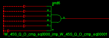
&W_45S_Q[7:2]
means a logical and of bits 2, 3, 4, 5, 6 and 7 of W_45S_Q. Remember that W_45S_Q was declared as having 8 bits, 0 though 7 but in this instance we only care about a subset of 2 though 7. The statement above is equivalent at the hardware level to a 6 input and gate connected to bits 2, 3, 4, 5, 6 and 7 of the W_45S_Q address bus. You can use the ISE project View RTL Schematic and navigate to W_45S_Q and see the actual hardware gate being used for synthesis for that statement:
Similarly a 3 input OR gate could be specified as
|W_45S_Q[6:4]
and a 7 input XOR gate as
^W_45S_Q[6:0]
There is no equivalent shorthand VHDL notation to specify this Verilog logical operation on a bit field:
&W_45S_Q[7:2]
So in VHDL we have to expand this to:
W_45S_Q(7) and W_45S_Q(6) and W_45S_Q(5) and W_45S_Q(4) and W_45S_Q(3) and W_45S_Q(2)
Conditional statements
One Verilog line equals ten VHDL lines?
Both Verilog and VHDL have if-then statements and they work the same as in any programming language. There is however a Verilog construct identical to the C language ? conditional operator:
result = condition ? 7 : 3
This assigns result the value 7 if condition was true otherwise result would be assigned the value 3 if condition was false. The equivalent VHDL construct would be
result <= 7 when condition else 3;
But there is a subtle difference. The ? conditional operator in Verilog can be used both synchronously (in a process) and asynchronously (combinatorial), whereas in VHDL, when-else can only be used asynchronously.
For example in Verilog this is a valid statement:
result = condition ? 7 : 3
Equivalently in VHDL this is a valid statement:
result <= 7 when condition else 3;
However inside a process, this is a valid Verilog statement:
always@(posedge clock) result = condition ? 7 : 3
But the equivalent VHDL will produce parse error, unexpected WHEN, expecting SEMICOLON during synthesis
 process(clock)
 begin
     if rising_edge(clock) then
         result <= 7 when condition else 3; -- this will not work !
     end if;
 end process;
So the solution in VHDL is to revert back to if-then statement as follows:
 process(clock)
 begin
     if rising_edge(clock) then
         if condition then
             result <= 7;
          else
             result <= 3;
         end if;
     end if;
 end process;
You can clearly see now that a one line Verilog statement has become a ten line piece of VHDL code.
Concatenation
Quirks of the language
Concatenation is a pretty simple concept, a number of bits can be concatenated into a bit field, for example suppose you have a 16 bit address bus W_A:
Verilog:
A = {3'h0,W_A[15:0]}
VHDL:
A <= "000" & W_A(15 downto 0)
In Verilog a concatenation is indicated by curly brackets around a coma separated list of bit values or bit fields. In VHDL you simply use the & symbol between the bit values. The symbol & does not mean logical and in VHDL. The net effect in the example above is that we end up with a bit field consisting of 18 bits: the three zero bits followed by the 16 bits of the address bus.
Now let's look at some more complicated examples, some of which are a single line in Verilog but may require multiple lines when translated to VHDL.
In Verilog it's possible to assign a logic equation to a wire while simultaneously declaring that wire for the first time. This can be done anywhere in the body of your module.
Verilog:
 module test(
 "blah verilog code..."
 wire   [7:0]W_LRAM_A = W_45T_Q^{8{W_H_FLIP1X}};
 "blah more verilog code.."
 endmodule
In VHDL you first have to define the signal in the architecture section of your module, before using it later in the body of the module. While you may have seen VHDL code that defines a signal and assigns a value to it, such as:
signal reset : std_logic := '0';
That assignment is only used for initialization at simulation time and you can not assign a complex logic equation to it at signal declaration time. The above Verilog code becomes:
VHDL:
 entity test is
     port ( ) end;
 architecture RTL of test is
     signal W_LRAM_A : std_logic_vector(7 downto 0);
 begin
     W_LRAM_A <= (W_45T_Q xor x"ff") when W_H_FLIP1X = '1' else W_45T_Q;
 end RTL;
Additionally in this example we see another Verilog specific construct 8{W_H_FLIP1X} which means, take the bit value of W_H_FLIP1X and concatenate it with itself 8 times, so if W_H_FLIP1X = 1 then you end up with a bit field "11111111". This can't be easily done in VHDL, so a conditional statement is used to xor the register W_45T_Q with "11111111" or hexadecimal FF when W_H_FLIP1X = 1
In the next Verilog example below, the and operation on the W_2M_Q in negated by ~ therefore producing a 4 input nand gate. The one bit result of that is concatenated with the bit W_VID_RAM_CSn and further concatenated with 10 zero bits producing a 12 bit field. This matches the width of W_VID_RAM_AA exactly.
Verilog:
wire [11:0]W_VID_RAM_AA = {~(&W_2M_Q[7:4]), W_VID_RAM_CSn, 10'h00 };
Converting this to VHDL below, we have to first declare the signal W_VID_RAM_AA before we use it. Since there isn't a direct VHDL construct to and the bits in a bitfield together like we can do in Verilog, I chose to expand it and and all the bits individually. This would have been quite awkward if it been a 16 bit and gate like for example Verilog construct &W_A[15:0] as it would have produced too much code.
VHDL:
 architecture ...
     signal W_VID_RAM_AA : std_logic_vector(11 downto 0);
 begin
     W_VID_RAM_AA  <= (not ( W_2M_Q(7) and W_2M_Q(6) and W_2M_Q(5) and W_2M_Q(4))) & W_VID_RAM_CSn & "0000000000";
     ...
 end;
Finally, we have another perfect illustration of compact Verilog code that can not be represented equally compact in VHDL. This one line Verilog code contains nested conditional statements:
Verilog:
W_SDAT2 <= W_6T_Q[2]==1'b0 ? 8'd0 : I_VOL1 ? 8'h69 : 8'h39 ;
The only way to represent that one liner Verilog logic in VHDL is to expand it and use if-then statements:
VHDL:
 if W_6T_Q(2) = '0' then
     W_SDAT2 <= (others => '0');
 else
     if I_VOL1 = '1' then
         W_SDAT2 <= x"69";
     else
         W_SDAT2 <= x"39";
     end if;
 end if;
Sensitivity lists
Triggering off of both rising and falling egdes of signals?
Just like me, you might come across a fairly common situation that most novices encounter sooner or later. You declare your signals in the process sensitivity list then you want to trigger conditional statements off them at both the rising and falling edge of a signal. Take for example the actual Verilog code below that synthesizes correctly:
Verilog:
 always@(posedge W_5P2_CLK or negedge I_SLDn)
 begin
     if(I_SLDn==1'b0)
         W_5P2_Q <= 1'b1;
     else
         W_5P2_Q <= 1'b0;
 end
At first crack you might convert it to VHDL like I did:
VHDL:
 process(W_5P2_CLK, I_SLDn)
 begin
     if rising_edge(W_5P2_CLK) or falling_edge(I_SLDn) then
         if (I_SLDn = '0') then
             W_5P2_Q <= '1';
         else
             W_5P2_Q <= '0';
         end if;
     end if;
 end process;
This is all syntactically correct until you try to synthesize the code and you get the infamous error:
Signal W_5P2_Q cannot be synthesized, bad synchronous description. The description style you are using to describe a synchronous element (register, memory, etc.) is not supported in the current software release
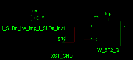
This simply states that you cannot use both the rising edge and the falling edge of a signal inside the same process within the same if-then statement. How can that possibly be? After all it works in the Verilog code above just fine. Well it is at this point that you have to slap yourself out of thinking like a programmer and start thinking like a hardware engineer. What does that code describe at the gate level? If you look carefully at the Verilog code, you will realize that the output W_5P2_Q will be set whenever signal I_SLDn falls and conversely the output will be cleared whenever W_5P2_CLK rises but only if I_SLDn is high at the time.
Can you see yet what type of hardware this implements? Spoiler.... it's a D-type set-reset flip-flop with the input tied low, W_5P2_CLK is the active on rising edge clock signal and I_SLDn is the active low asynchronous (pre)set. Another way to cheat is to synthesize the Verilog code then use the ISE project View RTL Schematic and navigate to the above code. Look at the schematic displayed and if you trace the signals you will recognize the circuit of a flip-flop.
Once you realize that, it becomes very simple to write equivalent VHDL code that implements this function like so:
VHDL:
 process(W_5P2_CLK, I_SLDn)
 begin
     if (I_SLDn = '0') then
         W_5P2_Q <= '1';
     elsif rising_edge(W_5P2_CLK) then
         W_5P2_Q <= '0';
     end if;
 end process;
This will now synthesize and function correctly, just like the Verilog code.
Instantiation
A mixed VHDL/Verilog environment
When tackling a project such as this, I didn't just convert everything from Verilog to VHDL in one go, I instead converted it one file at a time, then simulated or tested the code until it was functioning correctly, then moved on to translate the next file. As that process progressed I moved away from a homogenous Verilog environment to a heterogenous (mixed) environment where my project contained both Verilog and VHDL code. There are now some issues to consider such as how do you instantiate a module written in Verilog from VHDL and vice versa. Suppose we have the following hierarchical structure:
 galaxian_top.vhd
  +-roms.v
    +-rom0.vhd
We have VHDL instantiating Verilog modules which in turn instantiate VHDL modules. Let's start with the easy example:
In file rom0.vhd we have the module definition:
VHDL:
 entity ROM_PGM_0 is
   port (
     CLK  : in  std_logic;
     ENA  : in  std_logic;
     ADDR : in  std_logic_vector(13 downto 0);
     DATA : out std_logic_vector(7 downto 0)
     );
 end;
Which then in file roms.v we instantiate with:
Verilog:
 ROM_PGM_0 U_ROM(
 .CLK(I_ROM_CLK),
 .ADDR(I_ADDR[13:0]),
 .DATA(ROM_D),
 .ENA(1'b1)
 );
It looks pretty easy, let's now look at instantiation in the other direction.
In file roms.v we have the module definition:
Verilog:
 module GALAXIAN_ROMS(
 I_ROM_CLK,
 I_ADDR,
 O_DATA
 );

 input I_ROM_CLK;
 input [18:0]I_ADDR;
 output [7:0]O_DATA;
So in file galaxian_top.vhd we try to instantiate that module with:
VHDL:
 roms : GALAXIAN_ROMS
 port map(
     I_ROM_CLK            => W_CLK_12M,
     I_ADDR(18 downto 16) => "000",
     I_ADDR(15 downto 0)  => W_A(15 downto 0),
     O_DATA               => ROM_D
 );
But at synthesis we get an error Undefined symbol 'GALAXIAN_ROMS'. If we try to change it to an entity like so:
roms : entity GALAXIAN_ROMS
We get GALAXIAN_ROMS is not an entity name. It turns out, to correctly instantiate a Verilog module from VHDL you have to declare a component with the same name. The full correct instantiation then is:
VHDL:
 architecture RTL of galaxian_top is
 component GALAXIAN_ROMS is
 port (
     I_ROM_CLK : in  std_logic;
     I_ADDR    : in  std_logic_vector(18 downto 0);
     O_DATA    : out std_logic_vector( 7 downto 0)
 );
 end component;
 begin
 roms : GALAXIAN_ROMS
 port map(
     I_ROM_CLK            => W_CLK_12M,
     I_ADDR(18 downto 16) => "000",
     I_ADDR(15 downto 0)  => W_A(15 downto 0),
     O_DATA               => ROM_D
 );
 end;
Conclusion
The conversion of Galaxian from Verilog to VHDL was 100% successful and resulted in a functioning game entirely in VHDL. There are still a couple of minor tweaks and optimisations that could be done. As I've said before, I'm still learning VHDL and I welcome any constructive comments and suggestions.
Alex