
Hardware | Papilio DUO - Papilio One - Papilio Pro - MegaWings - Wings - Shields
1-Axis Stepper Motor Controller Wing
Purchase the 1-Axis Stepper Motor Controller Wing in the Gadget Factory Store.
Applications
- Position Control Systems
- Robotics
- Plotters and Scanners
Revisions
Version 1.0: It was a very small sized board without the silkscreened table showing current settings. Because of smaller copper area, it had to be derated to 1.5A instead of 2.5A. We have a few of these boards around (PCBs only) if any one is interested.
Version 1.2: First successfully tested working prototype, it was green in colour.
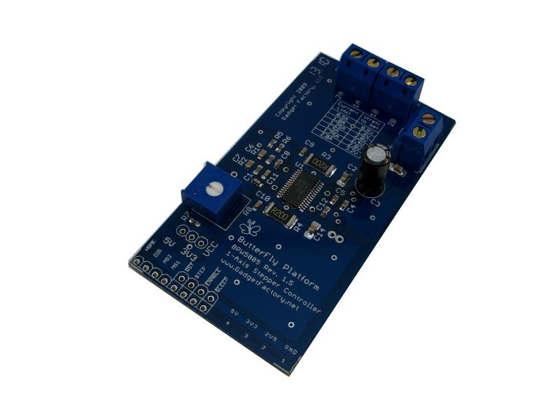
Version 1.5: Production version, updated the silkscreen markings and was made in blue as all GadgetFactory power boards are.
Version 2.0: While v1.5 are intended to be used with Cocoons for development purposes, version 2.0 adds mounting holes to it so that they can be used independently as well. There are no design changes to this board.
Specifications
- Integrated Stepper motor driver with dual H-bridge and built-in translator with microstepping support
- �2.5 A, 35 V output rating
- Full, Half, Quarter and Eighth (with DRV8811) or Sixteenth (with A3979) step modes
- 3.0 to 5.5 V logic supply voltage range
- Slow, Fast or Mixed current decay modes
- Home output
- Synchronous rectification for low power dissipation
- Internal UVLO and thermal shutdown circuitry
- Crossover-current protection
- Easy step/dir interface to host controller
Pinouts
| Pin | Name | Direction | Function |
|---|---|---|---|
| 1 | /SLEEP | Output | Active low input to put device into low-power mode when not in use |
| 2 | /ENABLE | Output | Active low input to allow power output |
| 3 | STEP | Output | A rising edge on this input advances the motor by one step (see MS2:MS1) |
| 4 | /RESET | Output | Active low input, resets internal counters and disables output |
| 6,5 | MS2:MS1 | Output | Microstep selection, can select full, half, quarter or eighth/sixteenth of a step |
| 7 | DIRECTION | Output | Sets direction of the motor |
| 8 | HOME | Input | Output indicates initial state of the internal translator, indicating one electrical rotation |
The Prototype and BOM
PCB Manufacturing Info: PCB is 1.6x3 inch, double sided PTH, glass epoxy 2 oz/sqft laminate, with ident and components on the top side. Minimum track width is 8 mils. Minimum track spacing is 10 mils. Minimum hole size is 0.5 mm.
Bill of Materials
| C1, C8, C9, C10, C11, C13 | 0.1uf/50V, 0603 |
| C2 | 0.1uf/50V, 1206 |
| C3 | 47uF/50V, Al-electrolytic |
| C4, C5, C12 | 0.22uF/50V, 0603 |
| C6, C7 | 680pF/50V, 0603 |
| R1, R2 | 56K, 0603 |
| R3, R4 | 0.2E/2W, 2512 |
| R5 | 3.3K, 0603 |
| R6, R7 | 2.2K, 0603 |
| U1 | A3979SLP or DRV8811PWP |
| VR1 | 10K, Bourns 3386 type |
| J1 | 2-way Phoenix connector for Motor power |
| J2 | 4-way Phoenix connector for Motor windings |
| JP1 | Jumper |


Using 1-Axis Stepper Motor Controller Wing
This Wing uses a 8-bit segment on a Butterfly Cocoon, like the S3E FPGA Cocoon.
The board has ample copper area for heat dissipation from the tiny A3979 (or DRV8811) with thermal vias on the underside of the chip to transfer heat from the exposed thermal pad.
- Use JP1 to select logic IO voltage between 5V or 3.3V that depends on the host device or the Cocoon.
- Microstep selection inputs can be set from your host i.e. the S3E FPGA pins to appropriate value.
- The logic inputs nRESET, nENABLE, nSLEEP, MS1, MS2 do not have any built-in pullup/pulldown resistors. They must be externally set to their active values.
- Phoenix connectors (terminal blocks) are used for easy integration of power sources and stepper motors.
- Variable resistor VR1 is used to set the current limit by setting the voltage that can be measured on the pad adjacent to the potentiometer. Resistor R7 ensures that the reference voltage stays within safe limits. The equation for current limit is:
Operational Limits and Precautions
- The maximum value of motor voltage recommended is 30V, and maximum recommended current limit is 2.25A, that is lower than documented limits. The 2.2K resistor R7 can be replaced with 5.1K one to ensure that the reference voltage never goes above 3.3V, to make maximum allowable current as 2.1A
- Do not move the stepper motor shaft when power is off as it can generate high voltage transients that may exceed 35V limit of the motor controller IC, leading to damage.
- Do not set too high a current limit for a given load at required speed as this may lead to overheating of the controller IC. Current draw is directly proportional to the load and required torque. Torque is inversely proportional to the speed at given current limit. Refer to your motor data for optimal settings.
- Always start at low speeds and gradually accelerate to desired speed, as torque output of the motor is high at lower speeds that can be used to overcome load inertia and get it into motion.
FPGA support
While this controller Wing can be operated by discrete IO signals from the FPGA or a microcontroller, a special peripheral core for the FPGA is being developed that will take care of applying timed pulses to the controller and also manage acceleration, deceleration and direction control through simple register interface. Please check the Stepper Controller Peripheral core project page.
Resources
Pictures
| Board Layout | Board Assembly |
|---|---|
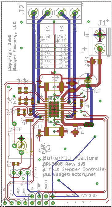 | 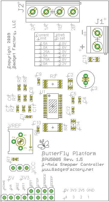 |
- Click image for PDF.
<< MIDIAudioWing | wings list | MicroSDWing >>